Since October 2014, I’ve been working with a team to investigate Hero (Heron) of Alexandria’s treatise On Making Automata (peri automatopoiētikēs). It’s not a very well known or well studied text, but it’s our best detailed evidence for a recognisable sub-field within ancient mechanics and engineering. The devices that Hero describes are powered mainly by falling weights that turn rotating axles and screws by means of cords, with some elements also powered by springs. These devices are thus distinguished from those described in Hero’s longer work, the Pneumatica, which are powered by water, wind or steam. The use of cords and axles also distinguishes these devices, as they are in a limited sense programmable.
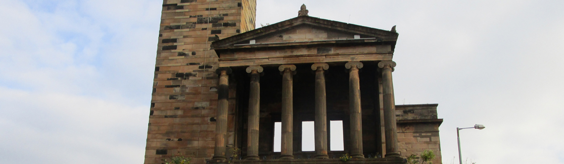
Hero describes two families of automata, mobile and static. The static variety is essentially a small theatre on top of a plinth (in which the falling weight is concealed) that presents a tragic narrative through a series of scenes with moving figures set against a variety of backdrops. This static (staton) model is, according to Hero, the older style of automata-making, which is transcended by the superior mobile (hypagon) type. The mobile form of automaton, which occupies the first two-thirds of the treatise, is a small circular shrine (with a central figure of Dionysos in the middle and a Nike on the roof) set on top of a plinth supported by four columns, with the weight falling down a central pipe (syrinx) and a base unit (basis) containing the wheels (for the case, see right). The basic configuration and scenario consists of wheels set up for straight-line motion (forwards or backwards); the unit moves to a certain point, stops, performs various activities—altars are lit, maenads dance and play tambourines, a figure of Dionysos shoots wine out of his cup and milk out of his thyrsus; Dionysos and the Nike rotate 180 degrees; more fire, fluids and dance—then it moves back to its starting point. Hero also gives instructions for more complex forms of motion (circular, rectangular and snake-like) as well as refinements for additional range (more cords and weights; a kind of primitive gearing system using additional small-diameter axles driving larger-diameter drums).

Our project has three main aspects. Most fundamentally, we’re trying to establish whether these automata could have been built (which is certainly claimed by Hero) and what sort of knowledge or expectations a reader of the treatise would have needed in order to put Hero’s instructions into practice (as an example, see figure 2: straight-line wheel configuration). If we can build them successfully, then we want to see what they are like, and what they can offer in terms of performance. We aim to be as scrupulous and clear as possible about how we are going about this, what our specifications are and what assumptions we have made (or have been forced to make).
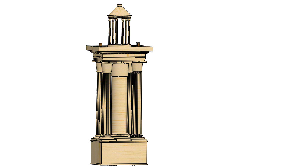
As a first step, Duncan is modelling the device in the 3D design package SolidWorks, before we hand the specifications over to technicians in the workshop of the School of Engineering to produce the components. We are being assisted by Euan, who has been patiently advising us on matters such as friction, rope bend and screw thickness, to name but a few highlights. We’ll be publishing 3D-models and animations and also scaled-down STL files if anyone wants to try 3D printing or adapting their own automaton. The images in this post are exports from SolidWorks.
The other two strands are more traditional: a translation, edition and commentary by Francesco, and a contextual volume, which I’ll be producing, on automata in antiquity and which also presents the results of the project. Both these elements feed into the design process, as there has been quite a bit of linguistic and archaeological investigation already in order to work out what exactly Hero is trying to say at a number of points. The surviving manuscripts do have diagrams—and diagrams of some sort are clearly presupposed by the text—although we have not felt bound by them where they do not represent a compelling interpretation of the text. These diagrams form the basis of those found in the Teubner edition of Schmidt (archive.org and gallica); tor examples, the British Library have made available some of their manuscripts which contain diagrams (Burney 108, Harley 5605, Harley 5589; my thanks to Cillian O’Hogan for the links), although they are quite late (like the majority of manuscripts preserved for this work).
We’ve been working mainly on the mobile automaton in the past year. We have modelled the basic drive mechanism and the four different wheel configurations that Hero discusses, along with the case. We re currently yet to model the figure of Dionysos, including his cup and thyrsos and associated pipes and reservoirs, the altars that need to be ignited, and the maenads that have to dance around the sanctuary. So far, we’ve learned a lot about what Hero does and doesn’t tell the reader. Apart from the overall dimensions of the case (and the important performance advice not to make it too big, so that no-one thinks you are hiding someone inside to drive it), there are almost no measurements in the treatise, nor indeed are many of the basic wood or metal-working techniques described, all of which are assumed, as are such practical matters of how and where to provide access to the innards of the automaton in order to set it up and configure it. Hero implies that all the different configurations belong to the same automaton, but this is clearly not possible simultaneously: there just isn’t room. So we have decided on a method to swap in and out different wheel and axle combinations.The silences suggests that he can assume such knowledge on the part of a technically-minded readers.

Yet the basic configuration looks eminently workable. Hero gives some important warnings in relation to the bearings, both about materials and lubrication, that demonstrate a serious practical concern for friction, which is a key factor if the mobile automaton is actually to move. To this end, he does not use the typical bearing used in ancient axles (the khoinikis: a bronze collar around the rounded ends of the (square cross-section) axle), but thin iron pins (knōdakes) set into the axle and which rotate in small-diameter sockets (empyelides). Hero’s choices here suggest a concern for practical application. It is interesting that he develops this line of argument particularly in relation to ‘snake-like’ motion (fig. 3), which instead of one single powered axle, has two independently powered axles for right and left wheels. Although Hero uses this for only modest changes of direction, his ideas here prefigure a differential drive, which can provide a complete solution to changes of direction in modern robots. Hero, however, achieves more dramatic changes of direction with specific configurations for circular and rectangular motion.

Rectangular motion (fig, 4) involves two sets of wheels set at right angles, which are alternately lowered and raised. This is by far the most problematic of the configurations Hero describes, and his failure to address some of the practical issues (including the thickness of the screw needed, or the requirements in terms of materials) suggests to us that Hero did not ever build this particular refinement. We believe we have a working configuration, however, and look forward to seeing whether we are right.
The project, funded by the Leverhulme Trust, is scheduled to run until November 2017. We’ll be posting updates here as we go, and we’ll be launching the project website, with translations, diagrams and videos once we’ve finished building the mobile automaton. .